Cold Plate Technology
To select the best cold plate for your application, you need to know the cooling fluid flow rate, the fluid inlet temperature, the heat load of the devices attached to the cold plate, and the maximum desired cold plate surface temperature, Tmax. From these you can determine the maximum allowable thermal resistance of the cold plate.
First, calculate the maximum temperature of the fluid when it leaves the cold plate, Tout. This is important because if Tout is greater than Tmax, there is no solution to the problem.

Alternatively, you can use the heat capacity graphs in our technical reference. These graphs describe the change in temperature, ![]() T, that occurs along the fluid path. To find Tout, add
T, that occurs along the fluid path. To find Tout, add ![]() T to the inlet temperature, Tin.
T to the inlet temperature, Tin.
Assuming Tout is less than Tmax, the next step is to determine the required normalized thermal resistance ( ![]() ) for the cold plate using this equation:
) for the cold plate using this equation:

Any cold plate technology that provides a normalized thermal resistance less than or equal to the calculated value will be a suitable solution.
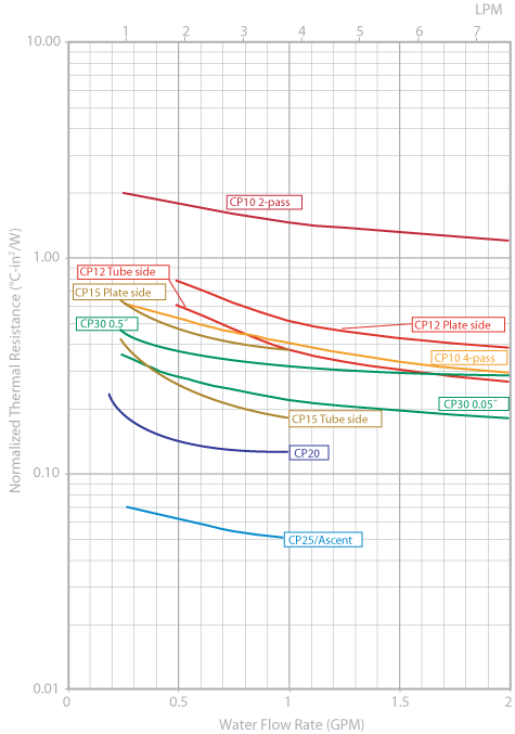
Example:
A cold plate is used to cool a 2˝ x 4˝ IGBT that generates 500 W of heat. It is cooled with 20°C water at a 0.5 gpm flow rate. The surface of the cold plate must not exceed 55°C.
We know:
Tin: 20°C, Tmax: 55°C, Q: 500 Watts, Area: 8 in2
We need to calculate Tout and ![]() .
.
First calculate Tout. Using the heat capacity graphs in our technical reference, we can see that the temperature change for 500W at a 0.5 gpm flow rate is 4°C. Therefore Tout = 20°C + 4°C = 24°C.
Tout is less than Tmaxso we can proceed to the second part of the problem. The required thermal resistance is given by this equation:


